Author: Johnson Controls Building Efficiency

About Johnson Controls Building Efficiency

Vice President Johnson Controls Building Efficiency

Ducted or non ducted air systems

Designing High Performance Duct Systems

Introduction

Ducted or non ducted air systemsFor the past 50+ years, engineers have been “designing” duct systems. Quite often, they were not actually designing the duct system, but were sizing duct the duct according to some rules of thumbs. The rules of thumbs varied by different engineering firms and often ducts were sized to be round by a predetermined friction rate that was chosen by the engineering firm. Then if the round duct did not fit and sometimes when it does, it’s often converted to rectangular, making it a lot less efficient system. Often, the whole ductwork system is “sized” that way using a Ductulator. Not much thought is given to the fittings used and often leakage of the system is not considered during the design phase.

Duct Design General Concepts

So how do we go about designing duct system to be green? There are many aspects to design, but focusing on the duct system design we want a system that minimizes the use of energy, time and material and make sure it meets the acoustical requirement of the application. To accomplish these goals we have to consider what the duct system will be used for (standard air conditioning, exhaust, or other), duct system layout, fitting selection, system leakage, acoustical properties and equipment selection.

There are three common methods of duct sizing or design for commercial and industrial duct systems: equal friction, static regain and constant velocity. Both the supply side (positive pressure) of the fan or air-handling unit (AHU) and the return side and makeup air side (negative pressure) of the fan have to be considered. The equal friction method and constant velocity systems can be used for either the supply or return side. Most often equal friction is used on the supply and the return systems while constant velocity is used for exhaust systems that have to convey particulate or fumes. Static regain however is strictly used for a positive pressure design.

This article will focus on the design of the duct system on the positive side of the fan or Air Handling Unit (AHU). Other important aspects that that should be looked at during the design phase may include fan or AHU selection, system effects, leakage, diversity, room air distribution, equipment layout and commissioning. Those are topics for other papers.

spiral duct


Choosing a Duct Design Method

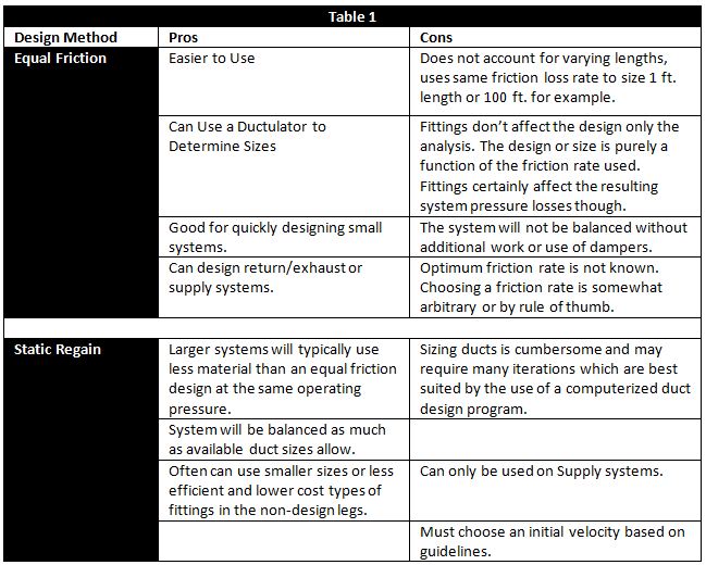
When we design duct systems we want the design method that minimizes energy, material and time. But first to dispel a myth, static regain does not automatically design systems at a lower total pressure. Any design method can be used to design a duct system for almost any pressure. A 6-in wg system can be designed either by Equal Friction (just increase the design friction rate) or by Static Regain (just increase the initial velocity). In either case though the velocities should be kept within acceptable limits to avoid noise problems. But a static regain design goal is to produce a balanced system. That is, one in which all paths are design legs, or require the exact same amount of static pressure for the legs respective airflow. For final balancing of systems, smaller sizes in non-critical paths will use excess pressures. So if two designs of the same system are created that have the same operating pressure, one with equal friction and one with static regain, the static regain method should use smaller duct sizes, because it is balancing the system. When this is the case you will likely have the benefit of more round sizes and because smaller sizes in general are used for balancing the non-design paths, the benefit of lower duct and fitting cost as well. A benefit of round duct is it has lower breakout noise, resulting in a quieter design. Another benefit is that round duct and the resultant smaller sizes are easier to install and seal. Some pros and cons of the two design methods are shown below:

Table1--


Total Pressure Design

Whether a system is designed with Equal Friction or with Static Regain, there is still likely to be imbalance. There should be less with the Static Regain design, but because in the real world we don’t have an infinite number of duct sizes, there is always some imbalance. Using the Static Regain design though helps to minimize this imbalance. Ideally we want all paths to be critical paths. That would mean the system is perfectly balanced. With imbalance means some paths will have more pressure (excess) available than they need, which means they likely have sections that can be made even smaller. Note to designers less efficient fittings will generate more noise, but that is generally not a problems till you get close to the final runouts. It’s best to design with high quality fittings that have lower pressure drop, then use smaller sizes. Using multiple runs of round rather than rectangular or flat oval duct could save even more money on the job. The process of taking a given design, determining the excess pressures available in the non-design legs, and making them smaller to use up the excess pressure, is often referred to as a total pressure design. It can be applied to any design method, but is most suited to be applied to the Static Regain Design method since it should already be fairly balanced. The good news is some of the duct design programs pinpoint the critical legs making it easy to identify where there will be excess pressure.

Example of Using Equal Friction vs Static Regain vs Total Pressure Design

In an article published by the Air Conditioning, Heating and Refrigeration News in their June 18 1990 edition, a system was designed with the Equal Friction sizing method with three different friction rates (0.05 in wg/100 ft., 0.10 in wg/100 ft. and 0.50 in wg/100 ft.). Then each of these three systems was designed with Static Regain, then the Total Pressure design. The system design airflow is 26,800 cfm and the designs were such that the Static Regain and Total Pressure methods had about the same operating pressure as the respective Equal Friction designs. The first section was the same size in all design methods. The results of the three designs are given in the Table 2:

Table2--

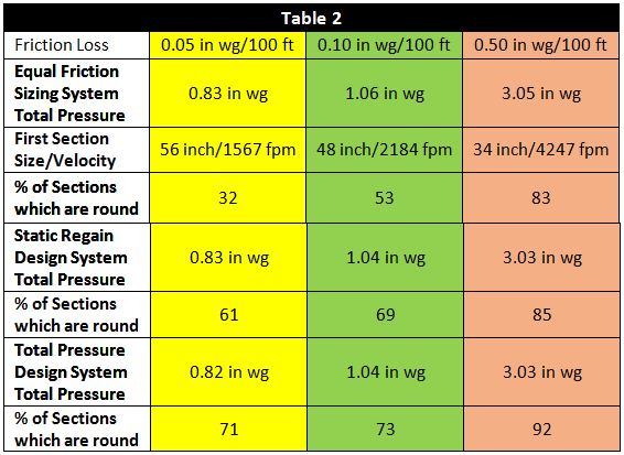
The system had a 12-inch height restriction. For the 0.05 in wg/100 ft Equal Friction design, the percent of sections that became round went from 32% to 61% by using the Static Regain design method and 71% for the Total Pressure design. Similar results can be seen for the two higher pressure designs as well.

Round ductwork cost much less than rectangular or flat oval, saves installation time, is easier to seal and the Static Regain and Total Pressure design methods are much more balanced!

The other advantage of total pressure design is that since it is a balanced system using smaller sections of duct which have higher attenuation and insertion losses. So using that knowledge, and keeping the velocities reasonable, total pressure designs should not require as much noise control.

Leakage

A high performance duct design should minimizing leakage. ASHRAE recommends the system leakage be no more than 5 percent of the total airflow volume. Why is that so important? If a system leaks and airflow requirements are not met in the locations they were intended, the leaks either have to be sealed or the fan speed must be increased to generate more volume. If the leaks are not sealed, a practice which is no longer allowed by many codes, that additional volume will need to be pushed through with a higher static, because remember that the system will continue to leak and that the airflow volume, plus the additional leakage airflow volume caused by higher static pressures will need to be overcome as well. Essentially you are changing the system curve from what was designed to what is actually happening.

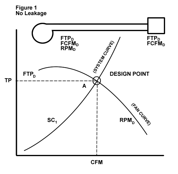
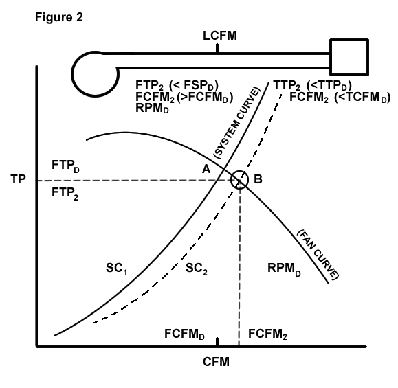
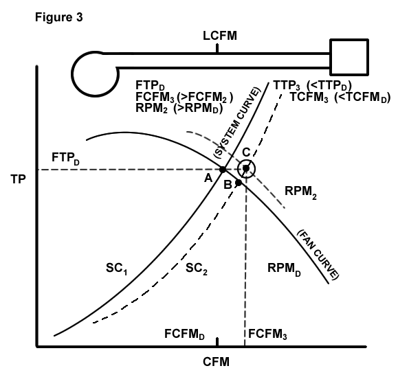
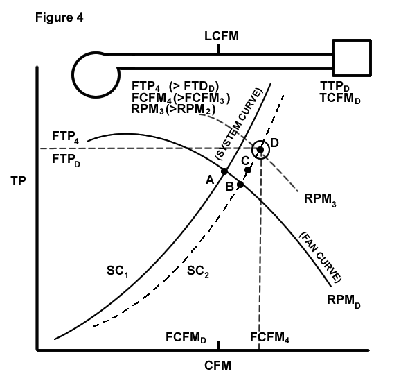
The design point for a fan is where the system curve crosses the fan curve as shown in Figure 1. It assumes no leakage is occurring. If there is 10% system leakage, the duct system is essentially relieved and the system curve moves down. That is because the same volume of air does not have to move through the entire system as some has leaked out. The airflow increases while the Fan TP decreases as shown in Figure 2. We can’t just speed up the fan as shown in Figure 3 so it produces the same original Fan TP as leakage is still occurring. We will actually have to move to a higher RPM and increase both the Fan TP and the airflow so we get the correct airflow to the outlets as shown in Figure 4.

ASHRAE studies have shown the cost of leakage could be $0.00050 per cfm-hr. So a 50,000 cfm system operating 2600 hrs per year with 10% leakage of 5000 cfm, could cost an additional $6500 per year.

 FIGURE1  FIGURE2
 FIGURE3  FIGURE4

Summary

To design high performance duct systems that do not have acoustic sound problems we need to

  • minimizes the use of energy
  • minimizes the use of construction/manufacturing labor and material
  • make sure it does not contribute noise to the environment
  • design balanced systems

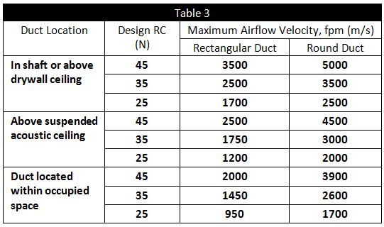
To best meet these objects, the Static Regain/Total Pressure design should be used to determine the duct sizes in a system. To use the Static Regain method, you have to choose an initial velocity. It is recommended you use the follow chart published in the ASHRAE Applications Handbook 2011, Table 8, page 48.14.

Table3


Then use Static Regain to size the duct sections, utilizing the most efficient fittings. When finished designing, use the Total Pressure design to further balance the system using smaller sizes and less efficient fittings in non-critical paths.

The final result will be a well-balanced system using the smallest sizes possible for the initial velocity. Smaller duct sizes mean:

  • more of the duct sizes will be round
  • round spiral duct is much easier to install and has fewer joints
  • many sizes will be smaller than those in other design methods, making even them easier to install and use less materials
  • smaller sizes will be easier and less costly to seal making very low leakage duct systems possible
  • the duct system will be balanced assuring everyone gets enough air and the Testing and Balancing peoples time will be minimized
  • done right, round ductwork results in quieter system with less risk of noise problems

You will likely need a computer to do the proper designs, but if you do; less time, material, and energy will be expended. With the proper controls and other components, the Static Regain/Total Pressure duct system designs are used in true High Performance Air Systems. What more could you ask for in a duct design.

Guest Blog Writer:

Pat Brooks, General Manager

esm

www.easternsheetmetal.com

The Benefits of Acid Etch Anodizing and how it is Superior to Caustic Anodizing

Acid EtchingRuskin continues to develop and optimize acid etch anodizing technology for louver production within its Juarez and Geneva plants.

Less Waste

Acid Etching is proven to be more environmentally friendly than the original caustic (alkaline) processes.  This is accomplished by reducing the amount of metal loss by up to 90% during the finishing process and resulting in less ‘sludge’ waste as a by-product culminating in lower disposal rates. Acid etching also conserves water, using lower amounts during the steps of rinsing as the caustic process demands several rinses. Some of the processes’ by-products are also recyclable and can be reused as one of the components that is made into aluminum.

A Superior Finish

Anodized Aluminum LouversA more consistent matte finish is also achieved by irregularities and imperfections such as extrusion lines or surface scratches being smoothed out to a level caustic anodizing cannot replicate. According to the Aluminum Anodizers Council, the process gives a finer more uniform pit distribution that is independent of the microstructure. This ultimately results in a better aesthetic appearance which can be extremely important in architectural products such as louvers. Less surface imperfections also mean a better tolerance to corrosion than previously achieved. With a smoother surface, anodize application will also result in a higher quality finish.  Solar glare from bright sunlight can also be reduced as gloss levels on the surface of the final product are decreased.


Better Production Times and Use of Resources

The complete acid etching procedure is more efficient over the traditional caustic etching resulting in an ultimate reduction of concentrated etching times by 80%. In taking less time to achieve the end result and needing lower tank temperatures, less plant energy is consumed making acid etch a more energy efficient process overall.

Acid Etching as a production process better meets the needs of Ruskin’s extrusion and preparation of its louvers for its customers, allowing it to provide a high quality aluminum product that requires low maintenance and inherently has a high resistance to corrosion.

Louver and Architectural Solutions

Aluminum louversWhile providing fresh air intake and exhaust, Ruskin Louvers can also provide different architectural styles to building design. With the variety of models, sizes, paint finishes available, and custom products, Ruskin Louvers can add unusual and appealing features to exterior and interior elevation. Ruskin louvers are available in depths ranging from 1.5″ to 12″ and can accommodate various blade angles with high free area.

Link to Ruskin Louver and Architectural Solutions

For more information about Ruskin’s complete louver product line, application and design support, and our state-of-the-art manufacturing capabilities, contact your local Ruskin representative nearest you or Contact Ruskin directly at (816) 761-7476.

Data Center HVAC Design Considerations

Data Center #HVACData centers today not only require protection from the elements, but also need to be designed to save energy as it is estimated they consume about 1.5 percent of all total demand. According to the Natural Resources Defense Council, data centers are one of the largest and fastest growing consumers of electricity in the United States. In the U.S in 2013 three million computer rooms used enough electricity to match the annual output of 34 large coal-fired power plants. Annual consumption is projected to increase by roughly 47 billion kilowatt-hours by 2020. The NRDC recommends that best-practice efficiency behaviours across the data center industry need to be adopted as demand rises to unprecedented levels.

Energy Savings in Data Centers through HVAC Equipment

Traditionally when a building needs cooling, compressors engage and fans start to move air over cooling coils. This cooled air is used to condition the internal environment where the temperature is required to be lowered. This process is extremely effective but requires costly compressor and fan energy, adding avoidable cost considering external building temperature is lower than the temperature inside. When the outdoor enthalpy (a combination of temperature and humidity) is preferred over the indoor enthalpy, conditions are suitable for “free cooling”.  Depending on the geographic location of the facility, economizer cooling can represents a dramatic reduction in overall energy consumption.

Economizer Data CenterWhat is an Economizer and how can it reduce energy usage?

An economizer is like a window that automatically opens itself – with the added advantage of going through the rooftop AC’s filtration system. An airside economizer simply recognizes the preferred enthalpy of the outside air. When enthalpy conditions are suitable for “free cooling”, the economizer controls position outdoor air, return air, and relief dampers to facilitate free cooling through the first and sometimes second stages of cooling.

Economizers can contribute to a reduction in data center power consumption by utilizing the cooler external building temperatures to assist in cooling the facility and equipment when required. In maximizing energy savings and reducing HVAC cooling load, the cooling system’s product life can be extended.

A study on building control systems by Battelle Laboratories found that, on average, the normalized heating and cooling Energy Use Intensity (EUI) of buildings with economizers was 13 percent lower than those without economizers. When an airside economizer works properly, the savings are significant. Whether your company is looking to burnish its environmental credentials, to lower the cost of operating its data center, or both, a properly designed system integrating an airside economizer is a cornerstone of achieving both goals.

Economizers and Indoor Air Quality (IAQ)

A confined, un-aerated indoor space within a building allows gaseous fumes, odors, germs, and even fungi to grow in concentration to the point that the indoor air is qualitatively different from the ambient air. IAQ is important because the health and the comfort of people working indoors are an important factor in sustainable productivity. Poor IAQ in a working environment can cause discomfort or health problems sometimes resulting in a loss of productivity, increased errors, and even litigation. With the added benefit of reducing cost in power consumption, introducing outside air into a building via economizers can also contribute to improving indoor air quality. Following the relevant ASHRAE standards that apply to ventilation, air movement and exhausting of contaminants ensures that IAQ requirements will be met. To meet the requirements of ASHRAE 62 the outside air entering a building should be measured and controlled.

The most important part of an airside economizer are the damper blades that allow the control and supply of a fixed amount of outside air into the building. Parallel bladed economizers do a better job of mixing the outside and return air to provide optimal benefit to the system.  The sealing ability of the damper is essential to the system as a whole, when contending with extreme temperatures external to the building. AMCA certified dampers can ensure leakage rates meet the appropriate standards.

It has to be recognized that during different seasons and in different climates the benefits from economizers may vary.

Relevant Codes and Standards applicable to Data Center HVAC

Ruskin EconomizerFeaturing Ruskin’s exclusive one-piece galvanized airfoil blade and stainless steel jamb, the Economizers provide low-leakage performance as described in ASHRAE Standard 90.1.  Each unit also features Ruskin’s “SUREFLOW” sensing tubes and blade position indicator to help determine minimum airflow.  This also helps assist in mixed air temperature verses blade position field adjustments.

Data Center Protection

The Natural Resources Defense Council states that Data centers can be regarded as the back bone of a modern economy serving businesses and communications. Defending data means not only protecting it from Mother Nature but also giving back to her with sustainable designs. A question that must be considered during the design of a data center, is ‘How likely could the facility be compromised in extreme weather conditions such as tornadoes and hurricanes?’

When evaluating potential HVAC equipment it is advisable to use FEMA rated louvers and grilles. FEMA rated grilles and hurricane-resistant louvers have been tested against high windloads and large missile impacts. Outside air control dampers can seal up the center when necessary to reduce humidity and heat.

XP500 FEMA GRILLERuskin’s XP500S Extreme Weather Grille protects wall penetrations from flying debris caused by tornadoes, hurricanes, and severe storms.  This type of protection is critical in the design of Community Shelters (ICC-500) and Safe Rooms (FEMA 361). It offers designers a ventilation solution for their near-absolute life safety requirements. The heavy duty grille can be mounted internally, externally, or in conjunction with other louvers providing protection and certified performance. Rated for an industry leading 266 psf windload, the XP500S Grille meets or exceeds the building envelope protection requirements while complementing the construction of data centers.

Relevant Certification

  • FEMA P-361, Safe Rooms for Tornadoes and Hurricanes
  • ICC-500 – ICC/NSSA Standard for the Design and Construction of Storm Shelters

For more information about Ruskin’s complete product line, application and design support, and our state-of-the-art manufacturing capabilities, contact your local Ruskin representative nearest you or Contact Ruskin directly at (816) 761-7476.

Guide for Facility Managers on the Testing and Maintenance of Fire Dampers

fire damperA fire damper can be defined as “a device installed in ducts and air transfer opening of an air distribution or smoke control system designed to close automatically upon detection of heat. It also serves to interrupt migratory airflow, resist the passage of flame, and maintain the integrity of the fire rated separation.” Its primary function is to prevent the passage of flame from one side of a fire-rated separation to the other.

The significant protection capabilities of fire dampers to life and property are now widely recognized by Facility Managers throughout the United States. More and more Authorities Having Jurisdiction (AHJ’s) and building owners are requiring fire dampers to be operational tested and maintained on a regular basis.

AHJ’s are requiring operational tests to determine if the damper will function when needed in order to resist the spread of fire. Operational testing normally involves removing or melting the fusible link and letting the damper close. Once the damper has proven to close, it is reopened and the fuse link replaced. All the dampers installed in a building must be tested prior to occupancy and again 1 year later under normal operating conditions. Reference NFPA 80 and NFPA 105 for more information.

Applicable Standards

NFPA 80 is the National Fire Protection Association standard that regulates the installation and maintenance of assemblies and devices used to protect openings in walls, floors and ceilings against the spread of fire and smoke within, into, or out of buildings.

NFPA 105 is the standard which prescribes the minimum requirements for smoke door assemblies and smoke dampers that are used as a means to restrict the flow of smoke though openings to provide safety to life and protection of property.

Fire Dampers must meet the UL555 Test Standard. UL (Underwriters Laboratories) states that the requirements of UL555 cover fire dampers that are intended for use where air ducts penetrate or terminate at openings in walls or partitions; in air transfer openings in partitions; and where air ducts extend through floors as specified in the standard for installation of air-conditioning and ventilating systems, NFPA 90A.

Testing and Maintenance

AMCA presents a valuable guide for commissioning and periodic performance testing of fire, smoke and other life safety related dampers. This guide provides recommendations for the proper commissioning of fire and life safety related dampers and details the appropriate intervals and methods for performing periodic performance testing of these dampers. This guide can be downloaded for free from AMCA’s website below.

AMCA Guide for Commissioning and Periodic Performance Testing of Fire, Smoke and Other Life Safety Related Dampers

To the facility manager operational tests and regular maintenance can present a couple of challenges:

  1. Most fire dampers are installed in areas of the building that are not easily accessible. Fire dampers are installed in penetrations of fire rated walls and floors as required by the building code and access to the damper itself is normally through an improperly sized access door.
  2. Fire dampers can be extremely difficult to test and reset due to their design (all manufacturers’ utilize the same basic curtain type design). There are two main types of fire dampers: dynamic fire dampers and static fire dampers. Dynamic fire dampers have been UL tested and proven to close against system air pressure and velocity. Static fire dampers, on the other hand, are UL tested but have not been proven to close against system air pressure and dynamic fire dampervelocity. The main difference between the two designs is dynamic dampers (in most cases) utilize springs to pull the curtain closed against the air pressure and velocity while static dampers rely solely upon gravity to pull the curtain closed (static dampers designed for floor installation utilize closure springs). The spring shape and size determine the air pressure and velocity against which the dynamic fire damper closes.

Dynamic fire dampers are becoming more popular with designers as dynamic dampers may be used in either a static system (fans off) or dynamic system (fans on) while static dampers can only be used with static systems.

Limited access and closure springs do not make dynamic fire dampers testing and maintenance friendly despite being life and property friendly as they are guaranteed to close if properly applied and installed.

A solution to the operational acceptance testing problems is to know the testing requirements beforehand. Coordinate with the AHJ and determine what they will accept for testing procedures.

Since dynamic dampers are proven to close, the solution may be a simple installation inspection to make sure the dampers are installed properly with no obstructions.

A solution to the maintenance testing is not so simple. Maintenance should be performed per NFPA80 and NFPA 105 requirements: “Each damper shall be tested and inspected after the damper is installed, then one year after installation. The maintenance testing and inspection frequency shall then be every 4 years, except in hospitals, where the frequency shall be every 6 years.”

Motorized fire damperMore often than not, the building will be occupied and access to the damper remains a problem; however the use of a motorized fire damper that can be operated from a remote, easily accessible location and can be equipped with position indication for operation verification. A motorized fire damper can be more easily maintained compared to a standard dynamic fire damper and contributes to maintenance and insurance savings. All motorized fire dampers are dynamic rated and may be utilized in place of any static or dynamic curtain blade fire damper.

Dynamic, multiple blade fire dampers provide another solution to the access and maintenance issues posed by the dynamic curtain blade dampers. Multiple blade fire dampers are easy to both test and reset since the blades can be operated and held open via a hand lever or a pair of pliers while the fuse link is replaced. An additional solution for round ducts is the use of a true round fire damper. Round fire damper allows the fusible link to be replaced easily then the damper can be adjusted to its full-open position.

Summary

Testing and maintenance of fire dampers, especially dynamic, curtain fire dampers, can be extremely difficult. There are, however, alternative types of dynamic fire dampers that make testing and maintenance easier. The cost of these other dampers is typically greater than standard dynamic fire dampers but savings can be easily realized in other areas like maintenance and insurance. Before designing around “standard” curtain type dynamic fire dampers, check with the Authorities Having Jurisdiction (AHJ’s) and the building owner to determine the testing and typical multi-blade dynamic fire damper maintenance requirements.

Ruskin Wireless InspectorRuskin Damper Testing Solutions

Ruskin can present a solution to your testing problems, our patented Wireless Damper Inspector system. Utilizing radio frequency, this remote control system cycles actuators of all life safety motorized dampers especially those that are installed in hard to reach or even inaccessible locations. Ruskin Wireless Damper Inspector satisfies NFPA requirements* for both initial and periodic testing of life safety dampers.

Ruskin Classic InspectorRuskin’s Classic Inspector™ consists of a Panel PC, UPS and pre-loaded software. The Panel PC communicates with damper interfaces to provide intelligent monitoring of motorized dampers and manual fire dampers. The data network cabling represents a substantial cost reduction when compared with conventional systems.

For more information about Ruskin’s complete product line, application and design support, and our state-of-the-art manufacturing capabilities, contact your local Ruskin representative nearest you or Contact Ruskin directly at (816) 761-7476.

Useful References

Miami-Dade County Approval Tests for Louvers

Louver Building Miami DadeThe South Florida Building Code (SFBC) states that products installed on the exterior of buildings must be designed to withstand the severe conditions produced by hurricanes. However, the widespread failure of various building products during Hurricane Andrew in 1992 identified a need for stronger code enforcement. Recognizing that standardized testing and product control could assist enforcement, the Metro-Dade County (later changed to include all of Miami-Dade County) Florida Building Code Compliance Office (BCCO) developed a series of test protocols that subject products to the rigors of hurricane wind and rain conditions.

Miami DadeTo gain Miami-Dade County Approval, louvers may be required to pass as many as four different tests — three are structural and one measures wind driven rain penetration resistance. These tests are referred to as PA’s or Protocol and Application Standards.

PA-100(A): Wind Driven Rain Penetration Test

The Building Code Compliance Office (BCCO) requires this test if the room the louver is installed in is designed to be dry (room is not designed to drain water and/or houses items that are not water resistant). This test subjects the louver to high velocity winds and heavy simulated rainfall. Using a wind generator and water jets that inject the equivalent to 8.8″ per hour rainfall into the airstream, 15 minute tests are run at wind velocities of 35, 70, and 90 mph. The final 110 mph test is performed for 5 minutes. The louver must allow no water penetration at 35 and 70 mph, and only .05% penetration at 90 and 110 mph.

PA-202: Uniform Static Air Pressure Test

If a louver is installed in a room that can drain water and houses water resistant items, the wind driven rain test is not required. Instead, the PA-202 test is performed. In this procedure, the louver is installed in a chamber and uniform static air pressure is applied in positive and negative directions. Several pressure levels are applied in increasing magnitude until a load equal to 1.5 times the design windload is attained. Pressures are sustained for 30 seconds. The deflection of blades, frames and supports is measured during the test and the amount of recovery is checked afterwards. Throughout the test the anchorage system is also monitored for failure. Design windloads for hurricane applications can produce static pressures in excess of 28″ w.g. If the room is considered a closed structure that cannot withstand this pressure or if it houses equipment that cannot handle the pressure, the BCCO code requires the louver/damper assembly be subjected to the PA-201 and PA-203 tests.

PA-201: Large Missile Impact Test

Impact on Miami Dade LouverThis test simulates wind-driven debris that is often present in hurricanes. In the test, the louver assembly is impacted with a 2″x 4″ board weighing 9 lbs. and traveling at approximately 34 mph. At least three separate impacts are conducted and the louver must prevent the board from both penetrating the assembly or creating a significant opening.

PA-203: Cyclic Wind Pressure

This test is conducted only after the Missile Impact Test has been done. By simulating the forces applied to a louver by repeated severe wind gusts, this test exposes possible weaknesses in the assembly created by the missile impacts. In this test, the louver assembly is installed in a chamber similar to the Uniform Pressure test. However, the pressures are applied for only a few seconds and repeated several hundred times. Pressure is increased until 1.3 times the design windload is achieved. As in the PA-202 procedure, the deflection of the components and the anchorage system are examined.

Miami Dade Louver Cross SectionRuskin’s Hurricane Louvers

Ruskin’s Hurricane Louvers are designed to exceed impact resistance and windload requirements with predesigned proven installation methods. Ruskin was the first manufacturer to gain Miami-Dade County approval for louvers. These louvers are built to withstand up to 160 psf on some products based upon the criteria in TAS 201, 202 and 203 as well as AMCA 540/550.

Hurricane Louver Products

For more information about Ruskin’s complete product line, application and design support, and our state-of-the-art manufacturing capabilities, contact your local Ruskin representative nearest you or Contact Ruskin directly at (816) 761-7476.

Damper and Air Economizer Leakage Requirements in U.S. Energy Codes and Standards Article

AMCA inmotion magazine supplementIn the AMCA inmotion magazine supplement to the Summer ASHRAE Journal the latest damper and air economizer leakage requirements in U.S Energy Codes and Standards are discussed in detail including California title 24.

This article illustrates how controlling the movement of air both in and out of a building is critical to ensuring proper IAQ (Indoor Air Quality) with the added benefits of minimizing energy consumption, averting condensation, and generally maximizing the total comfort levels of the building’s occupants.

The maximum allowable leakage requirements in energy codes and standards for non-residential building envelopes are examined.

The codes and standards covered are as follows:

Similarities and distinctions are highlighted between the damper leakage requirements in the 2015 IECC and the 2013 version of ASHRAE 90.1.

cd50 - Low Leakage DamperDampers are shown to be a key component in controlling air intake, exhaust and leakage associated with a building. The types of dampers covered include outdoor air intake and exhaust opening dampers, including those used for economizers.

It is concluded that to ensure compliance with all three building regulations, dampers and air economizers should be purchased with Class 1 performance certification under the AMCA Certified Ratings Program. Building owners and engineers can then be assured in the knowledge that the required leakage performance will be met by the dampers they specify meeting AMCA Class 1.

To read the complete article in detail from the AMCA inmotion magazine supplement Click HERE

Low leakage dampers Class 1Applicable Low Leakage Dampers

Ruskin offers both CD50 and CD60 Class 1A dampers. The CD50 damper is an extremely low leakage damper designed for use in medium to high pressure commercial HVAC systems.  It was the first AMCA licensed low leakage damper. The CD60 offers sturdy, steel construction with an interlocking frame design, enabling it to lock together without bolts, screws, or rivets that could shake loose.

For more information about Ruskin’s complete product line, application and design support, and our state-of-the-art manufacturing capabilities, contact your local Ruskin representative nearest you or Contact Ruskin directly at (816) 761-7476.

Schools and Outside Air Measurement

School Ventilation IAQIn the past, a common method to measure ventilation was to determine the difference between return air and supply air measuring stations. This difference was the approximate amount of outside air introduced into the building.

However, if each airflow-measuring station in the supply and return air was 3-percent accurate, an error rate of 6 percent for the total system air could result.

For example, if there is 100,000-cfm supply air system with a 6-percent error rate (or 6,000 cfm) compared to the requirement of 15,000 cfm outside air, the total error of the outside air system is 40 percent. This demonstrates the driving trend toward today’s more preferred system: direct measurement of outside air. By directly measuring outside air, the system designer minimizes the error and increases the accuracy.

In the last few years, several products have come into the market that are designed to directly control the outside air introduced into a building.

One method uses two outside air-measuring stations to control the outside airflow through the unit. One station is designed for 25-percent airflow and the other sized for 75-percent flow.

The control scheme is designed to keep the pressure signal viable for control. These stations stage their operation to keep the signal pressure useable, thus maintaining ventilation rates.

Another method integrates an air-measuring station into an outdoor air intake louver. Stability and control signals are amplified in this scheme, since air is measured at the highest velocity point in the outside air system. It is important that the manufacturer test this as a package. The louver can impact the performance of the air-measuring station if it is not designed and tested as a combination.

The fan-injection method consists of a separate fan and air-measuring station and is used to control the minimum outside air introduced into the HVAC system. These types of systems require extra space to install. Also, the extra energy required to operate the injection fan must be taken into consideration. It is possible that the injection fan could overpower the system and relieve air through the outside air damper.

Measuring and controlling outside air with an integrated air measuring station/damper assembly is becoming more popular. For constant-volume applications, these are usually set up to maintain minimum ventilation; a separate, standard damper for economizer operation obtains free cooling.
Accuracy is increased in measuring and controlling the minimum outside air versus the total air because the signal (or velocity pressure) from Pitot arrays is limited to 300 to 400 fpm on the low end. (The velocity pressure at that point is only 0.01 inches wg.)

Typical commercially available transducers have limited accuracy at these low pressures. By directly measuring and maintaining minimum ventilation rates, again the error rate is minimized.

louverMeasuring Air Quality

Ruskin has the most comprehensive line of air measuring and control solutions in the industry. Products include differential pressure probes for high velocity applications, combination units that measure and maintain flow, and highly sophisticated, intelligent solutions that incorporate thermal dispersion technology with microprocessor based controls that communicate with any building automation system.

For more information about Ruskin’s complete product line, application and design support, and our state-of-the-art manufacturing capabilities, contact your local Ruskin representative nearest you or Contact Ruskin directly at (816) 761-7476.

The Importance of Ventilation in Schools

Ventilation in schools IAQVentilation is perhaps the single most important element of an HVAC system. It influences air quality and energy efficiency, and proper ventilation controls odors, dilutes gases (such as carbon dioxide), and inhibits the spread of respiratory diseases. Ventilation air is critical in educational facilities.

Building codes dictate the amount of outside air that must be supplied to various spaces in such facilities. In the ASHRAE Handbook – HVAC Applications, the American Society of Heating, Refrigerating, and Air-Conditioning Engineers recommends that design considerations for education facilities must take into account that today’s schools are used for functions year-round. Adult education, night classes, and community functions put ever-increasing demands on these facilities. ASHRAE Standard 62 gives recommended ventilation rates for various spaces within educational facilities.

The environmental control system must be designed carefully to meet these needs. Many schools use gymnasiums as auditoriums and community meeting rooms, resulting in wide variations in use and occupancy rates. Flexibility is important in these multi-use rooms.

Ventilation Requirements

The code requirements are varied, but the new International Building Code (IBC) has been adopted by 44 states and will be the code most used in the future. The IBC gives data to determine the minimum outdoor airflow rate based on occupancy of the space and the occupancy load.

The occupancy load used for the design of the ventilation system shall not be less than the number determined from the estimated maximum occupant load rate indicated in the table. The ventilation system shall be designed to supply the required rate of ventilation air continuously during the period the building is occupied.

The minimum flow rate of outdoor air that the ventilation system must be capable of supplying during the operation of the system is based upon the rate per person indicated in the table. The IBC also addresses the special needs of variable air volume (VAV) systems and requires controls to regulate the flow of outdoor air over the entire range of supply air operating rates.

Measuring Air Quality

Ruskin Air Measuring Equipment

Ruskin has the most comprehensive line of air measuring and control solutions in the industry.  Products include differential pressure probes for high velocity applications, combination units that measure and maintain flow, and highly sophisticated, intelligent solutions that incorporate thermal dispersion technology with microprocessor based controls that communicate with any building automation system.

RSKN_Go_Green_Logo

For more information about Ruskin’s complete product line, application and design support, and our state-of-the-art manufacturing capabilities, contact your local Ruskin representative nearest you or Contact Ruskin directly at (816) 761-7476.

Ventilation Rate Procedure for HVAC Systems in the Healing Environment

Ventilation Rate IAQ Procedure - Air MeasuringThe IBC/IMC, the AIA, and Chapter 7 of the ASHRAE Handbook—HVAC Applications all reference ANSI / ASHRAE Standard 62 for determining ventilation. ANSI / ASHRAE Standard 62 provides two methods for engineers to follow to determine the required minimum ventilation rate to achieve acceptable indoor air quality.

To obtain compliance for ventilation design, there are two procedures in the ASHRAE standard. The ventilation rate procedure states that acceptable IAQ is achieved by providing ventilation air of the specified quality and quantity to the space. The indoor air quality procedure identifies a method for achieving acceptable IAQ within the space by controlling known and specifiable contaminants.

Ventilation Rate Procedure

The ventilation rate procedure provides a more definitive, prescriptive procedure based on physiological needs and subjective evaluations. The indoor air quality procedure uses guidelines for the specification of acceptable concentrations of certain contaminants in indoor air —with no prescriptive formula for ventilation rates.

The Indoor Air Quality (IAQ) Procedure

The indoor air quality procedure typically does not result in lower outside air in healing environment applications since the various potential sources of contamination require ventilation rates to be equal to that of the ventilation rate procedure. Additionally, the indoor air quality procedure requires the designer to specifically identify how each of the known contaminants is to be dealt with. The problem facing system designers with this procedure is in determining the possible contaminants that may result from the eventual use/occupancy of the healing environment. For example, controlling formaldehydes, aldehydes, nitrogen dioxides, organics, etc., all need to be understood and accomplished with “engineering reason” when tackling this method. As a result, most designers opt for the more common ventilation rate procedure (VRP ) to determine outdoor airflow needs at the space and system levels. This method prescribes the outdoor air quality acceptable for ventilation, outdoor air treatment where necessary, ventilation rates, and the criteria for reductions of outside air where recirculation treatments occur.

ASHRAE also addressed maintenance of outside ventilation systems. ANSI /ASHRAE Standard 62-2001 identifies minimum ongoing operation and maintenance criteria. The requirements of this section apply to buildings and their ventilation systems and their components constructed or renovated. In section 8.4 of ASHRAE 62, it states:

At a minimum of once every three months or as specified in the Operations and Maintenance Manual, the outdoor air dampers and actuators shall be visually inspected or remotely monitored and determined to verify that they are functioning in accordance with the Operations and Maintenance Manual.

ANSI /ASHRAE Standard 62’s definition of a maintenance manual is as follows:

An operations and maintenance manual either written or electronic shall be developed and maintained on site or in a centrally accessible location for the working life of the applicable ventilation system equipment or components.

This manual shall be updated as necessary. The manual shall consist, at a minimum, of the operation and maintenance procedures, final design drawings, operation and maintenance schedules, and any changes made thereto and the maintenance requirements.

Measuring Air Quality

Ruskin Air Measuring Equipment

Ruskin has the most comprehensive line of air measuring and control solutions in the industry.  Products include differential pressure probes for high velocity applications, combination units that measure and maintain flow, and highly sophisticated, intelligent solutions that incorporate thermal dispersion technology with microprocessor based controls that communicate with any building automation system.

RSKN_Go_Green_Logo

For more information about Ruskin’s complete product line, application and design support, and our state-of-the-art manufacturing capabilities, contact your local Ruskin representative nearest you or Contact Ruskin directly at (816) 761-7476.

Ventilation in Health Care Facilities #IAQ

Ventilation in Medical FacilitiesOutside air management is extremely critical in health care facilities. Today’s HVAC system designer has many choices when it comes to managing outside air. However, reviewing the requirements identified in the building codes permits the designer to focus on the control strategies that are compliant. With this knowledge, the HVAC designer can eliminate several alternatives and choose among the appropriate strategies.

ASHRAE, the American Institute of Architects (AIA), and the International Building Code (IBC) provide designers with the necessary IAQ standards and goals that will permit “acceptable indoor air quality,” but they are not intended to necessarily describe how to devise a ventilation system that applies these instructions to actual applications.

The Centers for Disease Control (CDC) recommends that ventilation systems be monitored to ensure proper ventilation, early detection of operational problems, optimized performance for particulate removal, and elimination of excess moisture. The CDC also advises that AIA and ASHRAE guidelines be used as minimum standards where state or local regulations are not in place for health care facilities.

IBC identifies requirements for ventilation that apply to all building types. Therefore, it is important that the system designer consult the ASHRAE Handbook—HVAC Applications, the AIA Guidelines for Design and Construction of Hospital and Health Care Facilities, as well as the IBC (or local building and mechanical codes). The Handbook further states that where higher outside air requirements are called for, they should be used.

Pressure Seal DampersIn addition to providing a controlled ventilation system that regulates and maintains a constant supply of design ventilation air, the HVAC designer must be cognizant of energy codes as well. A leakage criterion exists for dampers that are integral to the building envelope. More than half of the states have adopted the International Energy Conservation Code (IECC), referenced by the IBC. The IECC states that dampers integral to the building envelope “shall be equipped with motorized dampers with a maximum leakage of 3 cfm/ft² at 1.0 in. w.g. when tested in accordance with AMCA 500.” This requirement is only important for health care environments that are not occupied 24/7 (day care facilities, administration offices, doctor offices, etc.), as well as areas that utilize and require emergency lock-down systems.

Critical Air Paths

Ruskin PSD Pressure Seal Dampers are ideal for buildings with critical air paths including food facilities, federal buildings, pharmaceutical facilities, laboratories, hospitals, biotech labs, nuclear facilities, chemical process plants and military installations.

RSKN_Go_Green_LogoFor more information about Ruskin’s complete product line, application and design support, and our state-of-the-art manufacturing capabilities, contact your local Ruskin representative nearest you or Contact Ruskin directly at (816) 761-7476.